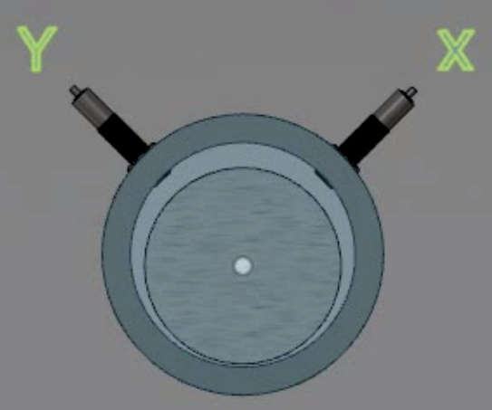
How do you use a Keyphasor(TM) to measure phase? We’ll answer that question in this short post.
Proximity probes, also called eddy current probes or displacement probes, are used to measure vibration in journal bearings. These probes are permanently installed in the bearing. They measure the distance between themselves and the shaft. Two probes are used on each bearing in order to get “X” and “Y” coordinates or a picture of how the rotor is moving in two axes. We also label the probes “X” and “Y”
It is important to label the X and Y probes correctly. There are different conventions for doing this, but the most popular one is to look from the driver towards the driven unit, with your head between the probes. Your right hand will point to the “X” probe and your left hand will point to the “Y” probe. Imagine that you are looking at the image above from the driver towards the driven unit. This is how the probes will be labeled under this convention.
You can rotate the bearing / probes any way you like as in the animation below. The X probe will still be “X” and the “Y” will be Y.
Measuring Phase with a Keyphasor
A third probe is typically mounted somewhere else axially along the rotor and is pointed at a key or a keyway. When the key or keyway passes the probe, the probe sees a big change in displacement (distance) and it creates a pulse. This once per revolution pulse is then used as a phase reference.
This 3rd probe is referred to as a “keyphasor.” This name was trademarked by Don Bently and Bently Nevada who developed much of this technology back in the 1960’s.
In the animation below, the probe on the left is the keyphasor and the probe on the top is for vibration. We are measuring phase from the moment the keyway in the shaft passes the keyphasor until the vibration probe reads its maximum level. This is the top of the sine wave. The vibration proximity probe reads its maximum level when the red heavy spot passes it. In the animation below, the phase is 90 degrees. Note that one cycle of vibration – eg from the peak of the sine wave to the next peak of the sine wave is 360 degrees. The phase here is 1/4 this distance.
For measuring phase with a keyphasor we are going to measure from the moment the key or keyway passes the keyphasor until each of the X and Y probes reads it’s maximum level of vibration. In the animation below, I have added a red dot called the “Heavy spot” which coincides with a mass unbalance in the rotor. This unbalance mass causes the rotor to vibrate. When the rotor is running well below it’s first critical speed, the X and Y probes will record their maximum values of vibration at the moment the red dot passes them.
Measuring Phase with a Keyphasor
You can pause the video above and move the slider until the keyway is aligned with the keyphasor on the right side of the rotor. This is your starting point. This is when the keyphasor puts out a pulse. The shaft is rotating counter clockwise. Now we need to ask how far (at what angle) do we need to rotate the shaft for the red dot to line up with the X probe and then with the Y probe. Those angles will be our phase angles.
The Y probe is easy because when the keyway is aligned with the keyphasor on the right, the red dot is at the Y probe and the Y probe is reading it’s maximum level. Therefore the phase angle at the Y probe is “0 Degrees.” We don’t have to rotate the rotor at all to get the red dot to coincide with the Y probe.
To get the X probe phase angle, simply consider the angle we need to rotate the rotor (counter clockwise) for the red dot to be under the X probe. This angle will be 270 degrees. Therefore, the phase angles we will measure on these probes are X = 270 degrees and Y = 0 degrees.
This is just a brief introduction to measuring phase with a keyphasor. There is a lot more to learn, and the best way to learn it is to sign up for one of my classes! And while you are at it, why not get certified?
Check out what else we have to offer…
Here’s a link to a YouTube video that describes these concepts in one short video. Please feel free to share it on social media and subscribe to my channel ( https://www.youtube.com/channel/UCSWbScnX0Bnb6iXbvtWAOSA ) so you’ll get notified when I add new content.
Sign up for a course here and get certified Cat 1, 2, or 3 in accordance with ISO 18436-2
https://zencovibrations.com/events/
Follow me on Linkedin to test your knowledge with free quiz questions.


